Despre vedetele de siguranta in "The Engineer":
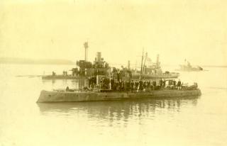
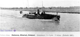
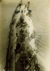
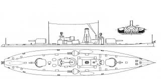
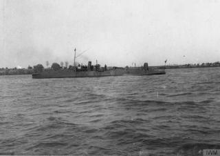
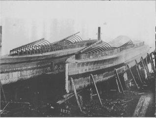
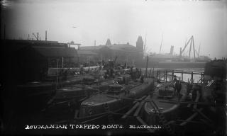
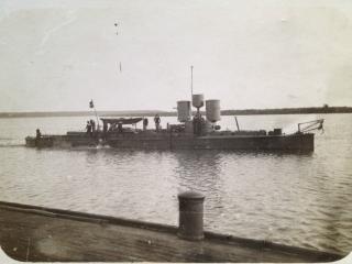
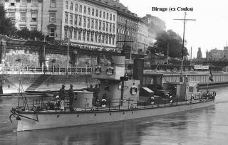
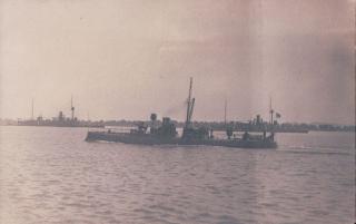
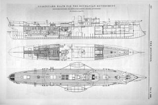
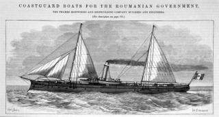
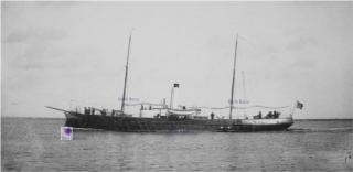
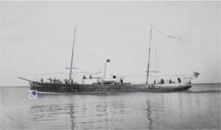
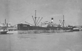
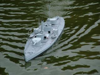
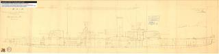
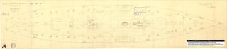
"On this page and on our two-page engraving will be found illustrations of a screw torpedo vedette-boat, eight of which have recently been built for the service of the Royal Roumanian Government by the Thames Iron Works, Shipbuilding, and Engineering Company Limited, London.
The vessels are 100 ft. long, 13 ft. beam, with a draught of water of 2 ft. 91/2 in., and a displacement of 51 tons.
The hulls are built throughout of steel, the deck and sides to just below the water-line being bullet-proof. The vessels are each fitted with a 47 millimeter gun on top of the conning-tower forward, and a small mitrailleuse gun aft.
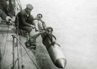
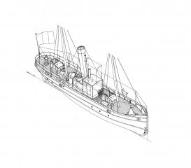
Gear for dropping torpedoes over the side is fitted on both sides amidships, and two spar-torpedoes are fitted forward over the bows. The boats are also supplied with powerful searchlight projectors, and are lighted throughout by electricity.
Accommodation is provided for four officers and twelve men.
The problem set the Thames Company was an extremely difficult one, the maximum length allowed being 100 ft.; maximum drought 2 ft. 91/2 in; and the speed 18 knots on a trial of four hours’ duration, under penalties. Owing to the abundant supply of oil in Roumania it was also desired to use petrol residuum as fuel.
It was found impossible to use internal combustion engines on account of their excessive weight, so it became necessary to provide the 600 indicated horse-power on a weight of 16 tons by using steam propelling machinery.
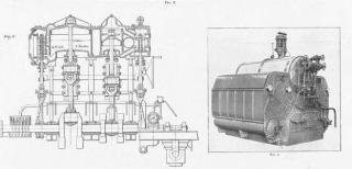
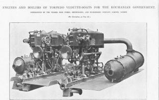
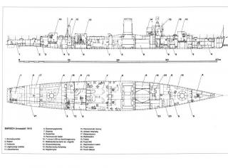
There are two sets of compound engines of the inverted type, the twin screws running in tunnels formed in the stern of the boat. These engines are shown in perspective in Fig. 2 on our two-page engraving, where may also be seen a longitudinal section of the engine in Fig. 3.
The cylinders are 81/2 in. and 17 in. in diameter respectively; with a stroke 9 in.and they are supported on turned-steel columns strongly braced together. The main bearing-frames are separate castings of Stone’s high-tension bronze of 30 tons per square inch tensile strength, bolted to long steel girders, which also carry the thrust-block, feed-pumps and air pumps.
The bearings throughout are lined with white metal, and centrifugal lubricators are fitted to all the revolving parts. The crank-shafts are solid, and balance-weights are fitted to the cranks. There are two feed-pumps fitted to each main engine, these being worked from s. counter-shaft driven by worm and worm-wheel from the crank-shaft at s. reduced speed, the pumps making one revolution to four of the engines. Each pump has a separate connection to the boiler through two non-return valves, and hand-controlled valves are fitted on the suction side only. This method of working is very simple, and is found to render the feeding of the boiler very safe and easy. There is also no danger of burst feed-pipes owing to feed-valves being inadvertently closed. The air-pumps are driven off the forward end of the crank-shaft through s universal joint, and run at the same speed as the main engine.
Each set of machinery is complete with its own condenser, and the centrifugal circulating pump, steam, exhaust, feed, and other pipes are all in duplicate, so that each main engine is entirely independent of the other.
The circulating pump has an impeller 12 in. in diameter, driven by a single cylinder engine. The pumps are entirely of gun-metal, and from each pump there is driven an auxiliary air-pump. which is so fitted that it can be stopped whilst the main air-pump is working.
The circulating water passes once through the condensers, and the condensers and pipes are arranged so that, with the circulating-pumps stopped, enough water will pass through the condensers to maintain a vacuum of 22 in. or 23 in.
There is s. hot-well tank at the forward end of the engine-room, and a reserve feed-tank at the after end, both being provided with filters. An auxiliary feed-pump, of the direct-acting type, by Messrs. Caird and Rayner. is fitted in the engine-room. It has a cylinder 71/2 in. in diameter, and a pump 51/2 in. in diameter, with a stroke of 8 in.
This is large enough to feed the boiler at full power, and will do duty for bilge or deck, and will pump through the filter on the reserve tank.
The propellers are of bronze. 3 ft. 3 in. in diameter, three-bladed, accurately pitched and balanced.
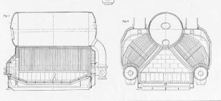
Steam is supplied by a Thames Iron Works water-tube boiler, the design of which will be seen by the illustrations on our two-page engraving, a perspective view being given in Fig. 4, and a longitudinal and transverse sections in Figs. 5 and 6 respectively.
The steam pressure is 185 lb. per square inch. and the heating surface 1290 square feet. The furnace is specially arranged for burning oil fuel. the ordinary fire-bars being replaced by fire-bricks with slots for the admission of air.
The casing is carried down under the hearth, and the air is admitted directly at the front, and at the back through a casing which serves the double purpose of keeping the back cool and of heating up the air before entering the furnace.
Owing to the very limited weight available for the machinery, it was necessary to resort to steam spraying. Four special burners are fitted tn each boiler, two at the top having an angle downwards, and two on the bottom, at each side of the fire-door, directed towards the centre. The arrangement of the oil and steam-pipes can be seen from Fig. 4.
Oil-bunkers are fitted on each side oi the boiler, and a steam-pump is fitted for pumping from them to the present-use tank. A steam-coil is fitted in each tank for heating the oil, the steam running first through the present-use tank, and then through the coils in the bunkers. The water from these coils is run into the bilge to obviate any danger of getting oil into the feed water.
Both bunkers and the present-use tank act as settling tanks, and a valve is fitted at the bottom of each to drain off water as it collects.
There is not enough height in the boat to run the oil through the burners by gravity; the present-use tank is therefore worked under an air pressure of from 1 lb. to 10 lb., the air being supplied by a small pump driven off the fan-engine, and a reducing valve regulates the pressure.
The forced-draught fan is 4 ft. in diameter. driven by a single steam-engine running at 300 to 1000 revolutions per minute, the air pressure at full power being from 4 in. to 5 in. of water.
For the purpose of securing good ventilation in the engine-room the air inlet of the fan is through the upper part of the engine-room bulkhead, and the mushroom-topped ventilator at the aft end of the engine-room. The air for the boilers has thus to pass right through the engine-room, serving admirably to ventilate that compartment.
In the steering compartment is the generating set for lighting the ship and working the projector. The 8 kilowatt dynamo was made by the Thames Iron Works electrical department, and the enclosed tandem compound engine. made by Messrs. Peter Brotherhood, Belvedere-Road. Lambeth, S.E. has forced lubrication.
Four bilge ejectors, each of 8 tons per hour capacity, are fitted, one in each compartment. Chadburn’s reply telegraphs are fitted from conning tower to both engines.
The boats were designed by the late Mr, G. C. Makrow, and the official trial of the first boat took place on the Thames, September 25, 1906.
The Roumanian Government were represented by:
- Major Demetriade, Director of Marine;
- Captain-Commander Balesco, President of the Commission;
- Captain Negru,
- Captain Mihail, and
- Captain Stefanesco.
The trial was of four hours’ duration, and the following results were obtained:
- Mean speed: 18.0365 knots
- Mean indicated horsepower: 622.7
- Mean revolutions per minute: 554.8
- Boiler steam pressure: 182.3 lb. per sq in,
- Air pressure in stoke-hold: 41/2 in. water
- Pressure of steam in oil-fuel burners: 181 lb. per sq, in,
- Pressure of oil for oil-fuel burners: 7 ""
- Temperature of oil in warming tank: 175 deg, Fahr.
- Oil consumption: 1.73 lb. per 1 H.P. per hour
This result was obtained with the two top burners only in operation. The power was maintained steadily, and generally there was absolutely no smoke or visible gases from the funnels.
The machinery, which was designed by Mr. R. Warriner, ran smoothly and without vibration; no sign of heating was observed in any of the bearings, although only the ordinary oil service was used. On the stopping and starting trial the engines were easily and rapidly manipulated by one man.
Four of these boats left the Thames Iron Works last October, taking altogether six weeks on their journey from London to Galatz through the waterways of Central Europe. They were not allowed to proceed under their own steam, but had to be towed along with the barges, &c. in the usual way.
The last four boats left the works in March, an are now on their way through the centre of Europe."
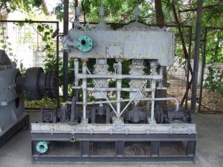
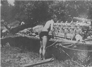
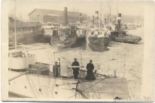
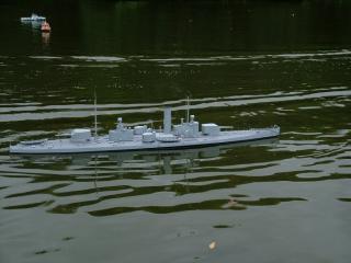
Masina aflata la MMR:
Aceasta postare a fost editata de 177: 05 April 2016 - 08:40 PM

 Ajutor

 177
177 


 Sus
Sus